You can use settings to individually customize the user interface and the program behavior in EPLAN Smart Wiring to your requirements and your working method. The following settings are available:
- You can select the desired color combination for the appearance of the user interface from various schemes.
- If you have completed the manufacturing work on a project, you can activate a check mode for quality control. In this mode the result of the check can be documented for each routing connection listed in the connection list.
- If the fully automatic wire fabrication machine "Rittal Wire Terminal WT" or the Rittal solution "Wire Station" with integrated cutting machine is integrated into your manufacturing process, you can set up EPLAN Smart Wiring accordingly and enable it for reading and outputting further machine-specific connection information via corresponding interfaces.
- If connection properties for the labeling of cable connections (cable conductors), wires (single conductors) or hoses are to be printed, the output data can also be determined and the font and font size can be selected.
- You can select the column layout of the connection list required for the respective project with the corresponding properties from a list of schemes made available to you by your administrator.
- You have the possibility to modify the color display of the buttons for the status assignment of the routing connections.
 Configuring a color scheme
Procedure
- Select the menu item Settings > Colors.
- Using the drop-down list User interface design select whether you want to work with a light or a dark user interface.
- The selected setting is applied immediately.
- Using the drop-down list Row height, choose between a large, middle or small height of the row representation in the connection list.
- The selected setting is applied immediately.
Note
The setting Small can be used to significantly reduce the row height for the displayed information of a routing connection in the connection list. This way significantly more routing connections can be displayed on the screen in the current display of the connection list.

Activating check mode
In the Check mode it is possible to document the quality of the installed wiring through the assignment of a check status.
Preconditions
- You have opened or continued a project of the *.EPDZ type.
- The project is completed, this means that all routing connections of the project have the status "Installed".
Procedure
- Select the menu item Settings > Check mode.
- Select the Use option.
- All routing connections which so far have been marked with the status "Installed"
 in the connection list now receive the status "To be checked"
  .
.
Note
If there are routing connections in the connection list of the project that have the status "Partially installed"  or "Not installed"
  , they are hidden in the connection list if the check mode is activated.
Activating interfaces
With the menu items Settings > Installation mode it is possible to enable EPLAN Smart Wiring for the data transfer for the manufacturing process with the fully automatic wire fabrication machine "Rittal Wire Terminal WT" and / or the Rittal solution "Wire Station" with integrated cutting machine.
Activating the interface to "Rittal Wire Terminal WT"
Procedure
- Select the Wire Terminal option in the Installation mode menu.
- The setting has the effect that when opening a project in the footer of the selection dialog you can have an additional Load "Wire Terminal" file check box displayed.
- In addition an additional menu item called Load "Wire Terminal" file is added to the project menu.
The settings allow downloading of the required connection information in the form of a CSV file that comes from the machine software and that was provided to you in a specific directory by the administrator.
Interface for the Rittal solution "Wire Station" with integrated length-cutting machines
- Select the Wire Station option in the Installation mode menu.
- This setting has the effect that when the detail view of a routing connection is opened in the connection list the
 button is shown.
With the button it is possible to provide data of the routing connection in the form of a CSV file for the cutting machine. The data is stored in a directory which is provided by your administrator.
Note
If the "Cable" connection type is selected for editing, both interfaces cannot be selected.
Setting the print output for the labeling of connections
In EPLAN Smart Wiring connection properties of routing connections for the labeling of cable connections (cable conductors), wires (single conductors), wire jumpers and hoses can be printed.
Preconditions
You have opened or continued a project of the *.EPDZ type.
Procedure
- Select the menu item Settings > Labeling.
- In the Labeling menu select the Output data option.
- In the subsequently displayed list select all the connection properties that you wish to print.
- Switch back to the Labeling menu and select the Font settings option.
- In the Font settings menu select the desired font size and font.
- Switch back again to the Labeling menu and select the option Data separator settings.
- In the Data separator settings menu specify one of the available separators for the output data during printing. In the User-defined field you have the possibility to define any character as the separator.
Notes
- Note that after the creation of a new project instance the output data Source, Target and Description is set as a default for the print output.
- The output data set by you for the printing are saved at the respective project instance. If., for example, a colleague logs into EPLAN Smart Wiring under their name and edits the same project instance, the settings for the previously specified output data are retained.
Selecting a column scheme for the connection list
Different information is often required project-independently when editing wiring jobs which have to be displayed as connection properties in the connection list. To this purpose your administrator provides different schemes in a selection dialog. They can be used to configure the column representation of the properties in the connection list project-specifically.
Notes
- After signing into EPLAN Smart Wiring the last selected scheme is automatically applied when opening or continuing a project.
- The scheme is saved user-specifically, this means if you have logged in under another user name, the scheme last used by this user is applied to all opened or continued projects.
- The selection of a column scheme is not possible when the "Cable" connection type has been selected.
Select column scheme
Procedure
- Select the menu items Settings > Select column scheme.
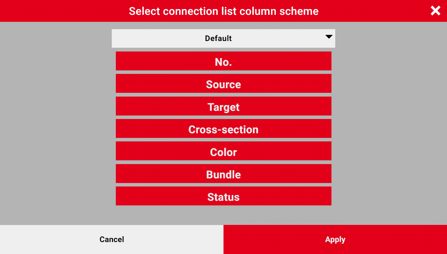
- The Select connection list column scheme dialog opens.
- Select the desired scheme name in the drop-down list.
- The column layout of the properties saved in the scheme is displayed as a preview in blocks below each other. The top block corresponds to the first column in the connection list and the bottom one to the last column.
- Click or tap [Apply].
- The selected scheme is applied immediately in the connection list.
Changing the representation of the status icons
Routing connections can have different installation statuses which can be visualized by means of icons. The representation of the status icons for the buttons and display in the connection list can be changed. An alternative representation in addition to the standard representation is possible.
Procedure
- Select the menu item Settings > Status icons.
- In the Status icons menu activate the menu item Use standard representation.
- The selected setting is applied immediately.
- Just deactivate the menu item to select the alternative representation.
The following tables show representations of the icons for buttons and displays in the connection list that depend on the settings.
|
Standard representation |
Status |
|---|---|
|
|
Not installed |
|
|
Partially installed |
|
|
Installed |
  |
To be uninstalled |
  |
Removed |
  |
Locked |
  |
Correction required (check mode) |
 |
Review required (check mode) |
  |
Checked (check mode) |


|
Alternative representation |
Status |
|---|---|
|
|
Not installed |
|
|
Partially installed |
|
|
Installed |
  |
To be uninstalled |
  |
Removed |
  |
Locked |
  |
Correction required (check mode) |
  |
Review required (check mode) |
 |
Checked (check mode) |


